
The process industry is characterized by closed systems that cannot be inferred easily from the outside, enormous process durations, and long ramp-up and ramp-down times. As a result, changes to process plants are even more costly than in discrete manufacturing. Careful planning is therefore required. However, data silos and data redundancies make planning difficult and result in huge manual effort. By leveraging the Asset Administration Shell to create a common data space, ProSys 4.0 aims to increase changeability by eliminating these silos and redundancies. As a result, ProSys 4.0 makes plant changes more predictable and less costly, dramatically increasing the competitiveness of companies. The Fraunhofer Institute for Experimental Software Engineering IESE primarily provides assistance to this project with expert knowledge about the Asset Administration Shell and supports the implementation utilizing the BaSyx DOTNET sdk as well as an extension of it tailored to the project.

Guest Author: Björn Höper (LTSoft GmbH)
Björn Höper is a passionate advocate for leveraging Information Technology in Manufacturing at LTSoft GmbH. His deep involvement revolves around harnessing automation system data to finely tune production processes. Through his company, he provides expert consultation and seamless implementation services, empowering clients to unleash the full potential of their production facilities.
Introduction
Process industry refers to the production of products primarily based on chemical and physical processes. The largest representative of the process industry is the chemical industry, whose major representatives are the refining and petroleum processing industry, the pharmaceutical industry, the pulp and paper industry, and the food and beverage industry. Typically, the products of the process industry consist of several input products that are processed in a closed system, which cannot be inferred easily from the outside. As a rule of thumb, end products in discrete manufacturing can be mechanically disassembled into individual parts, whereas this is not possible for products of the process industry. In addition, the duration of a process can take enormous amounts of time, in the range of years. During this time, constant supervision and monitoring must be guaranteed. In addition, the process industry is characterized by long-winded ramp-up and ramp-down times. Plant changes therefore require careful planning. However, data silos and redundancies make planning difficult. As a result, changes involve a huge amount of manual effort and a significant risk of financial loss.
The BaSys 4.0 satellite project ProSys4.0 aims to bring Industry 4.0 capability to the process industry, leveraging the Asset Administration Shell (AAS) to eliminate these redundancies and data silos by creating a common data space. BaSys 4.0 (hereafter simply referred to as BaSys) is a reference architecture for production systems that enables the transformation to Industry 4.0. It enables users to control assets, (e.g., machines but also individual components) by mapping their functionality in an Asset Administration Shell, which holds a digital representation of all functionality of the asset in the form of submodels. Therefore, BaSys can be seen as a value-adding accelerator in terms of digitalization and virtualization of the factory. Machines from different manufacturers can be easily integrated, so they can communicate with each other and comply with the BaSys specification. Another advantage of BaSys is its focus on retrofitting existing systems, i.e., upgrading and modernizing existing systems in terms of functionality and efficiency. The prerequisite for this is that the concerned assets provide a communication interface for data acquisition. The reference implementation of BaSys is the open-source project Eclipse BaSyx (hereafter simply referred to as BaSyx). BaSyx implements all necessary standards and infrastructure for Industry 4.0 production environments and provides the foundation for building tailored software platforms with a comprehensive Software Development Kit (SDK) and ready-to-use off-the-shelf components.
ProSys 4.0 is a research project using the reference implementation BaSyx to create value for the process industry. Here, the focus is not only on the application of the reference implementation, but on the adaptation and provision of new features to flow back into the main project. In addition, the retrofitting of existing plants and systems plays a major role in this project.
The implementation of the research project is coordinated by LTSoft – Agentur für Leittechnik-Software GmbH in cooperation with Fraunhofer IESE and pragmatic minds GmbH. The outcome will be deployed at INEOS Manufacturing Deutschland GmbH at its petrochemicals site in Cologne. INEOS is an important supplier of raw products to the chemical industry. Fraunhofer IESE’s contribution to the project focuses on expertise regarding the Asset Administration Shell, as well as support for the architecture and implementation of the project.
Challenges of the process industry
The process industry covers the area of producing products that consist of crude feedstocks, which are usually in liquid or gaseous form. In petrochemistry, typical source product candidates are crude oil and natural gas. In contrast to this, in discrete manufacturing, individual parts and semi-finished products are usually assembled at loosely coupled stations. Thus, in discrete manufacturing, it is easily possible to maintain individual stations even during operation. Such dynamic maintenance is not possible in the process industry since production takes place in a closed system. Furthermore, plants in the process industry involve extremely long ramp-up and ramp-down times, often in the range of several days or even weeks. Therefore, intervention during an ongoing process is not readily possible and is always associated with high risks and costs. In addition to a potential decrease in product quality and production loss, serious damage to humans and the environment may be the consequence of incorrect handling. For instance, pressure vessels may pose a risk of explosion. If the process is disrupted at an inopportune moment, unstable chemicals may react with the ambient air or other products, resulting in devastating explosions, deflagrations, or damage to inner parts of the plant in terms of permanent blockages or surface damage, which can remain undetected for years before it becomes apparent to the outside world.
Furthermore, the process industry differs from discrete manufacturing in terms of the engineering, assembly, and operation of a single plant. In this regard, multiple disciplines are required that each demand different information. Each discipline looks at widely differing sub-aspects of a single asset. As indicated above, the type and structure of an individual automation device is much more critical than for comparable parts in discrete manufacturing. With a process engineering valve, for instance, it is essential to consider the fluids that are passed through, and the interior design of the valve, which affects its control characteristics, is of immense importance. Therefore, it is essential that the information required by the involved disciplines remains available in a structured and revision-proof manner, even over the typically long lifecycles of several decades, in order to be able to access the configuration data of the elements in the event of maintenance or replacement. In addition, the plant data is usually distributed across several specialized tools, which create sealed data silos. In this context, the automation technology is realized by a Distributed Control System (DCS), which has a special status: In a DCS, all structures and measured values required for automation are managed. A DCS consists of a network of sensors and actuators, as well as process control technology and software for monitoring and controlling the process. It allows engineers to remotely monitor and control the entire process by observing and adjusting parameters such as temperature, pressure, flow, and levels. However, the necessary semantics are often missing, meaning that specialist knowledge is required for their interpretation. This leads to a lack of interoperability and makes managing the data difficult as neither the DCS, its configuration tools, or any other system has the possibility to provide a tangible view of an asset. As a result, only highly trained professionals with a wealth of experience are able to operate a DCS and interpret the data it provides. This in turn means that this knowledge is only available to a few people, which leads to a high risk of failure on the one hand and could mean a tragic loss of knowledge on the other.
The scope of application covers the disciplines of DCS engineers, Advanced Process Control (APC) engineers, Process Control Technology (PCT) engineers, and Maintenance engineers:
- DCS engineers have a higher-level view of the entire system. For example, they want to inspect the hardware setup of every component in a plant to quickly implement maintenance recommendations.
- APC engineers optimize process flows and therefore want to compare data from multiple historical sources in a unified way in order to improve the error diagnostic process.
- PCT engineers are responsible for the flow control structures of a plant, such as valves and pumps. Among other things, they want to get the configuration data for valves from the configuration data of the DCS.
- Maintenance engineers ensure that downtime is kept to a minimum and that maintenance activities are planned. For instance, they want to automatically get the configuration data for rotating equipment in order to derive an automatically updated configuration.
Towards a changeable process industry with the Asset Administration Shell
ProSys4.0 aims to improve the configuration and data management of process plants by using the BaSys 4 middleware. For this purpose, mechanical components, specifically valves and pumps, are mapped in Asset Administration Shells. The automation structure of the plant from the DCS serves as the basis for this. From here, the existence and configuration of the mechanical assets is depicted using a rule-based approach. This already saves considerable manual effort in maintaining the number of existing assets since all valves and motors remain in accordance with the automation structure. In order to achieve optimal manageability, assets are subdivided into different individual Asset Administration Shells. A “role” AAS is defined by its technical location in the plant and the function that an asset fulfills. Role Asset Administration Shells describe the tasks of each valve in the plant structure. At the role level, general tasks and requirements for the concrete mechanical element are defined. Moreover, a replacement history can be obtained here, which covers both the valve type and the valve itself. The role can be considered like an abstraction for a mechanical component. These mechanical elements are represented by two other Asset Administration Shells: a „type“ AAS and an „instance“ AAS.
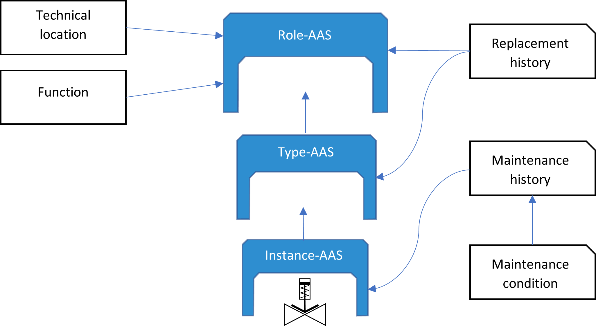
The type AAS describes the properties of a valve of a certain type in a general manner (materials, compatibility with fluids flowing through it, etc.) and also contains a replacement history, which only applies to the mechanical component represented by the instance AAS.
In contrast, the instance AAS provides the properties of a physical asset, like its serial number, maintenance history, and current maintenance condition, as well as further manufacturer information and inspection information.
This hierarchy of Asset Administration Shells ensures that a complete replacement and maintenance history can be viewed at any time, even if an instance or a type was replaced by another. The division into role and type + instance does, on the one hand, enable a historization of the valves installed in a specific position and, on the other hand, illustrates that the properties of the overall compound are composed of the individual properties on different levels. The Asset Administration Shells for rotating components are structured analogously. For users of the platform, the subdivision of assets into three Asset Administration Shells will remain completely unnoticeable, but they will benefit from having live data on the asset currently in use, as well as historical data on the overall maintenance and replacement history of an asset assigned to a particular role. The key factor for the realization of the platform is that it should not be noticeable to the user how many different AASs are used to map an individual object. Instead, this approach aims to significantly increase the overall user experience by enabling engineers to represent all relevant properties through a single projection.
In addition to the composition of role, type, and instance, it is of course also necessary and desirable to compose individual assets as composite elements, e.g., valve body, actuator, and positioner in the case of valves. For this purpose, a bill-of-material construct in the form of an Entity Submodel Element is used.
Solution architecture utilizing the Asset Administration Shell
To model the architecture, the lightweight C4 approach is used. The C4 model was created by Simon Brown. It provides hierarchical abstractions to communicate a system architecture at four levels of granularity: (system) context, containers, components, and (optionally) code.
- A context diagram offers an overview of the system under design and shows actors that might interact with the system.
- A container diagram “zooms in” and reveals the system’s applications, services, and storages. Container diagrams also show actors and other systems that interact with the containers, which are illustrated behind the system boundary. When the term „container“ is used below, a container in terms of the C4 model is meant and not some containerized software like a Docker container or similar.
- A component diagram contains the components of a container, i.e., what each of those components are, their responsibilities, and the technology/implementation details. Each component diagram optionally contains a code diagram. This could be a UML class diagram representing the structure of a component on a very low level. In addition, it is possible to create additional diagrams for different levels; e.g., UML sequence diagrams could complement component diagrams.
- A code diagram depicts the structural organization of a software component at the code level. This diagram is optional. For this purpose, it is possible, but not required, to use a UML class diagram.
Figure 2 shows the context diagram of ProSys4.0. In the center, we can see the ProSys System itself, with two actors above it. On the left side is the DCS, which is a System actor, on the right side is an X-Engineer representing all Engineer users (DCS, APC, PCT, Maintenance; in the future, the individual user roles will be broken down further and given their own use cases since reality does not exactly correspond to this draft, as different engineers will use different interfaces). The DCS provides live data of the current status and configuration to the ProSys System while an Engineer can read and adjust the current plant status as illustrated below.
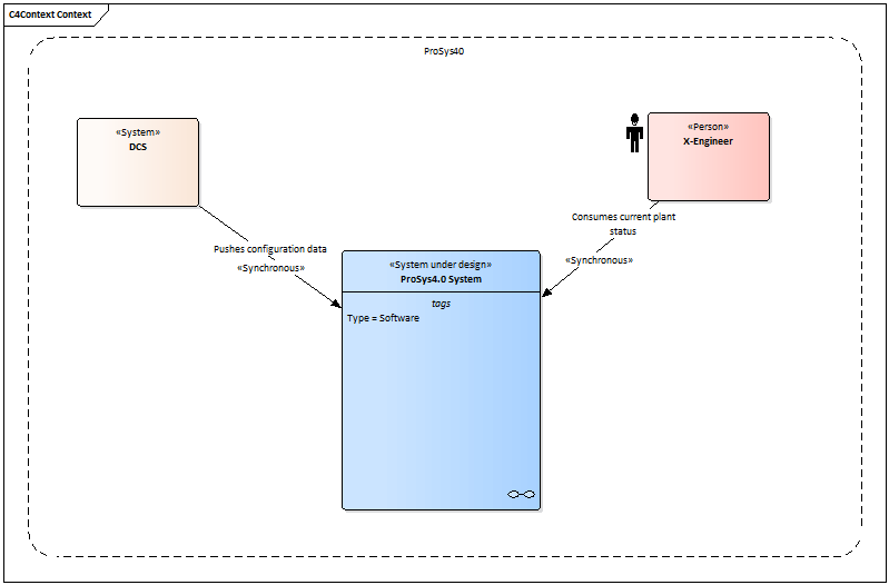
Figure 3 shows the first container of the ProSys 4.0 system from the perspective of the DCS. The DCS data is received by a „Configuration Producer“ container and interpreted and prepared for further processing. The configuration consumer processes the data and checks it for differences to the previous configuration. The pre-processed data is then passed to a data broker in the form of change events, as shown in Figure 3. The broker accepts push events and emits data itself, which can be consumed by any component by subscription.


The downstream container is the configuration consumer, as shown in Figure 5. It is subscribed to the broker and further processes the emitted data. Its task is to recognize the current configuration and extract configuration changes in textual form. The configuration changes are then written to a git repository and the current configuration is placed in both a time series database and a graph database, as shown in Figure 6. The time series DB serves as a chronological history that can be accessed to enable assessment or reuse of previous configurations at any time. The current status of the configuration is always stored on the graph DB. This is the productive data that will be actively worked with. Here, a graph database was explicitly chosen as it brings significant advantages in terms of data traversability, which is the most natural way to find related assets in a network of sensors and actuators.


Figure 7 shows the interaction with the system from an Engineer’s point of view. An Engineer consumes and potentially produces data via a frontend application. As mentioned above, there will eventually be more Engineer actors that will use different interfaces to interact with the system.
The frontend application uses an API application to access data from the graph DB as shown in Figure 8.


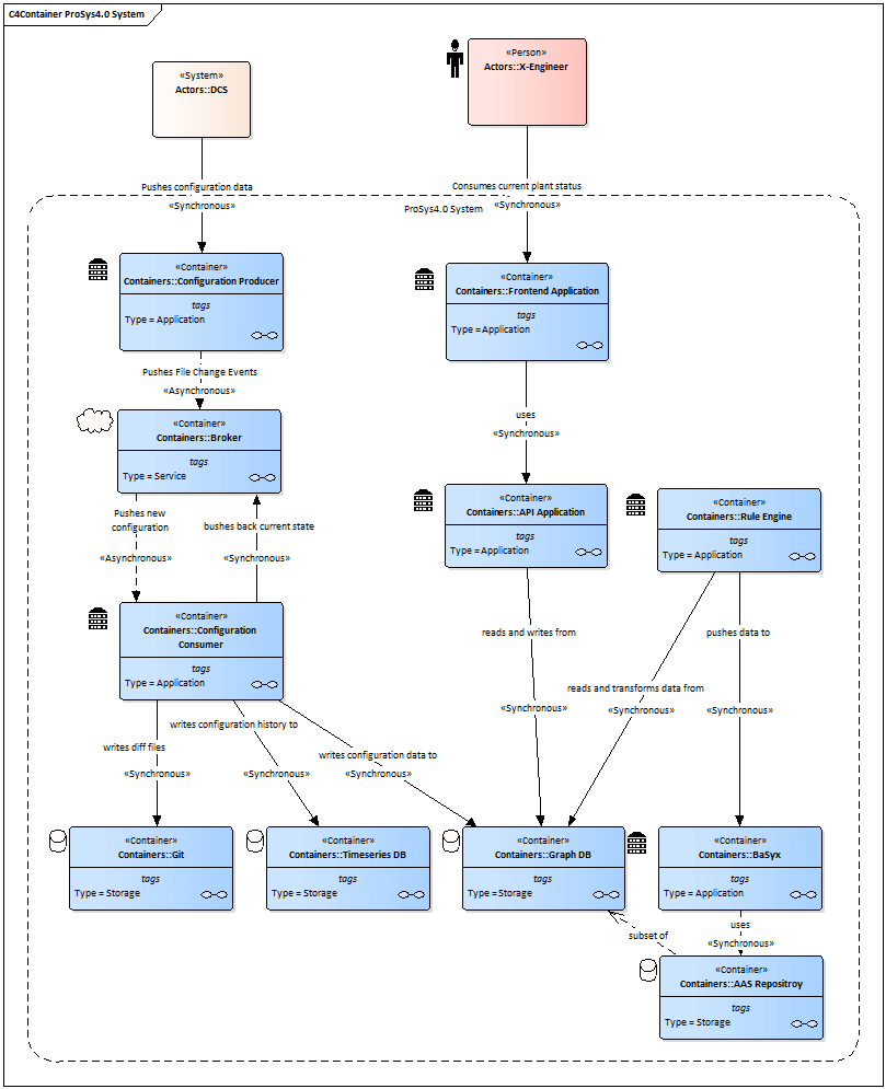
Finally, Figure 9 shows the container diagram of the ProSys4.0 system. At this point, the utilization of BaSyx is visualized, too. First, a rule engine accesses the current configuration status from the graph DB. Then the configuration is transformed by the rule engine into the corresponding Asset Administration Shells using the BaSyx SDK. The shells are stored in a BaSyx native AAS Repository, which is realized as a graph DB backend. IThis closes the full circle. The data an engineer accesses from the graph DB via the API application is directly provided by the AAS Repository. An AAS repository thus always contains an up-to-date representation of the system. For engineers, a web frontend serves as Human Machine Interface (HMI). The frontend accesses the graph database via an API application.
Next Steps
As a result of the solution explained above, the changeability of the process industry will be drastically increased. Especially the areas of usability and distribution of knowledge will benefit immensely. In consequence, ProSys 4.0 will help to decrease the cost and risk associated with plant changes.
The architecture is currently being worked out at a higher level of detail; for example, details such as other actors are being added. In parallel, implementation is currently taking place using the Eclipse BaSyx DOTNET SDK. In addition, the concrete definition of the required submodels is still pending.
After implementation, the project will initially be rolled out as a prototype at INEOS for testing and validation. It is expected that the project will be completed in the course of this year (2023). In a follow-up blog post, the comprehensive solution architecture of ProSys 4.0 will be detailed after the project is finished.

